
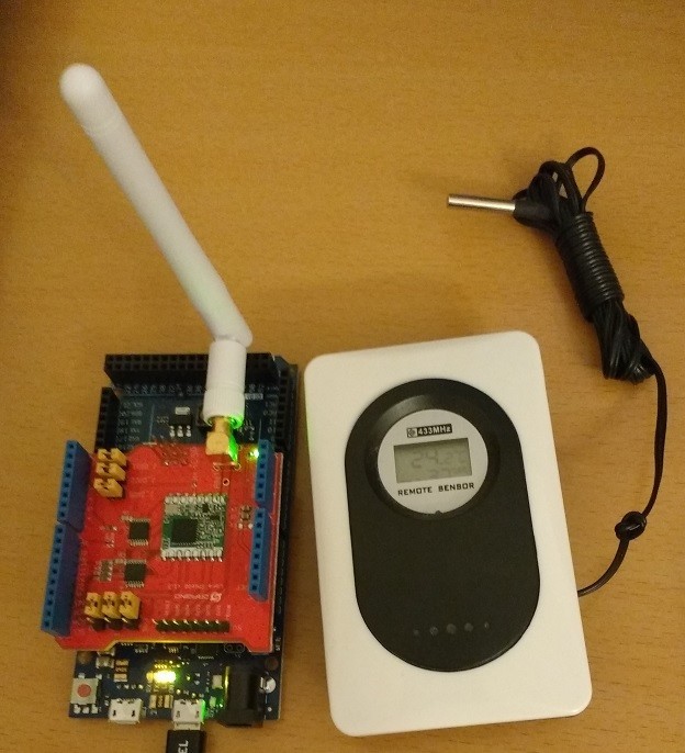
Dragino Lora Shield (Semtech SX1278)
Arduino Due
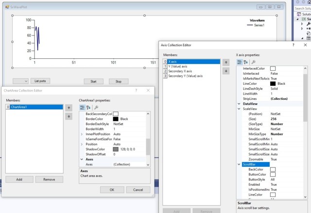
Visual Studio, C#
Arduino code
#include <SPI.h>
#define SERIAL_SPEED 57600
#define BPS 1200
#define FREQ 433.9855
#define STATE_SLEEP 0
#define STATE_STANDBY 1
#define STATE_FSRX 4
#define STATE_RX 5
#define S_DELAY 10
#define L_DELAY 100
#define CH_FILTER_BW B00001100 // 25 kHz
#define DCLK_PIN 6
#define DATA_PIN 7
#define RegOpMode 0x01
#define RegBitrateMsb 0x02
#define RegBitrateLsb 0x03
#define RegFrfMsb 0x06
#define RegFrfMid 0x07
#define RegFrfLsb 0x08
#define RegPaRamp 0x0a
#define RegRssiConfig 0x0e
#define RegRssiValue 0x11
#define RegRxBw 0x12
#define RegOokPeak 0x14
#define RegPreambleDetect 0x1f
#define RegSyncConfig 0x27
#define RegPacketConfig1 0x30
#define RegPacketConfig2 0x31
#define RegIrqFlags2 0x3f
#define RegDioMapping1 0x40
#define RegVersion 0x42
#define SX_OSC_FREQ 32000000
#define SX_RESET 9
#define SX_RESET_DELAY_H 5
#define SX_RESET_DELAY_L 100
#define SPI_SS 10
#define SPI_RW_DELAY 50
volatile uint32_t duration = 0;
volatile bool chg = false;
void setup() {
Serial.begin(SERIAL_SPEED);
if (initSX()) {
pinMode(DATA_PIN, INPUT);
pinMode(DCLK_PIN, INPUT);
delay(S_DELAY);
startFSK();
// OOK
uint8_t b = readSPI(RegOpMode);
bitClear(b, 6);
bitSet(b, 5);
writeSPI(RegOpMode, b);
// Channel filter bandwidth control
writeSPI(RegRxBw, CH_FILTER_BW);
setFreq(FREQ);
setBps(BPS);
// Bits 7-6: AutoRestartRxMode, 01 On, without waiting for the PLL to re-lock
// Bit 4: Enables the Sync word generation and detection: 0 => Off, 1 => On
// Bit 5: Sets the polarity of the Preamble. 0 0xAA, 1 0x55
// Bits 2-0: Size of the Sync word (SyncSize + 1)
b = readSPI(RegSyncConfig);
bitClear(b, 7);
bitSet(b, 6);
bitClear(b, 4);
bitClear(b, 5);
writeSPI(RegSyncConfig, b);
// Bits 6-5: Defines DC-free encoding/decoding performed: 00->none, 01->manchester, 10->whitening
// Bit 7: packet format, 0 = fixed length, 1 = variable length
// Bit 4: crc calc/check, 0 = off, 1 = on
// Bits 2-1: Defines address based filtering in Rx: 00 ïƒ None (Off)
// Bit 3: Defines the behavior of the packet handler when CRC check fails:
// 0 => Clear FIFO and restart new packet reception. No PayloadReady interrupt issued.
// 1 => Do not clear FIFO. PayloadReady interrupt issued.
// Bit 0: Selects the CRC and whitening algorithms:
// 0 CCITT CRC implementation with standard whitening
// 1 IBM CRC implementation with alternate whitening
b = 0;
bitSet(b, 7);
writeSPI(RegPacketConfig1, b);
// Bits 6-5: FSK data shaping:
// 00 -> no shaping, 01 -> Gaussian filter BT = 1.0
// 10 -> Gaussian filter BT = 0.5, 11 -> Gaussian filter BT = 0.3
// Bits 3-0: Rise/Fall time of ramp up/down in FSK:
// 1001 40 us
b = readSPI(RegPaRamp);
bitClear(b, 6);
bitClear(b, 5);
bitSet(b, 3);
bitClear(b, 2);
bitClear(b, 1);
bitSet(b, 0);
writeSPI(RegPaRamp, b);
// Data processing mode: 0 => Continuous mode, 1 => Packet mode
b = readSPI(RegPacketConfig2);
bitClear(b, 6);
writeSPI(RegPacketConfig2, b);
// Set DIO mapping
b = readSPI(RegDioMapping1);
bitClear(b, 5);
bitClear(b, 4);
bitClear(b, 3);
bitClear(b, 2);
writeSPI(RegDioMapping1, b);
// RSSI smoothing.
// Defines the number of samples taken to average the RSSI result. 000 -> 2 samples
b = readSPI(RegRssiConfig);
bitClear(b, 2);
bitClear(b, 1);
bitClear(b, 0);
writeSPI(RegRssiConfig, b);
// Bit 5: enables the Bit Synchronizer:
// 0 -> bit sync disabled (not possible in packet mode), 1 -> bit sync enabled
b = readSPI(RegOokPeak);
bitClear(b, 5);
writeSPI(RegOokPeak, b);
// RegPreambleDetect (0x1f). Enables Preamble detector when set to 1.
// The AGC settings supersede this bit during the startup / AGC phase.
// Bit 7: 0 -> turned off, 1 -> turned on
// Bits 6-5: Number of Preamble bytes to detect to trigger an interrupt.
// 00 1 byte, 10 3 bytes, 01 2 bytes
b = readSPI(RegPreambleDetect);
bitClear(b, 7);
writeSPI(RegPreambleDetect, b);
clearFifoAndFlags();
digitalWrite(DCLK_PIN, LOW);
digitalWrite(DATA_PIN, LOW);
attachInterrupt(digitalPinToInterrupt(DATA_PIN), isr, CHANGE);
setState(STATE_FSRX);
delay(L_DELAY);
setState(STATE_RX);
// delay(S_DELAY);
}
}
void loop() {
if (chg) {
chg = false;
Serial.println(duration);
}
}
void isr() {
static uint32_t lastTi = 0;
uint32_t ti = micros();
duration = ti - lastTi;
chg = true;
lastTi = ti;
}
void clearFifoAndFlags() {
// Flag(s) and FIFO are cleared when this bit is set
uint8_t b = readSPI(RegIrqFlags2);
bitSet(b, 4);
writeSPI(RegIrqFlags2, b);
delay(S_DELAY);
}
void setBps(uint16_t bps) {
uint16_t baudRate = SX_OSC_FREQ / bps;
writeSPI(RegBitrateMsb, baudRate >> 8);
writeSPI(RegBitrateLsb, baudRate & 0xff);
}
void setFreq(float f)
{
uint32_t lf = (f * 1000000) / 61.035;
writeSPI(RegFrfMsb, (lf >> 16) & 0xff);
writeSPI(RegFrfMid, (lf >> 8) & 0xff);
writeSPI(RegFrfLsb, lf & 0xff);
}
void setState(uint8_t s) {
uint8_t b = readSPI(RegOpMode);
b = b | s;
writeSPI(RegOpMode, b);
}
void startFSK()
{
setState(STATE_SLEEP);
delay(S_DELAY);
uint8_t b = readSPI(RegOpMode);
bitClear(b, 7);
writeSPI(RegOpMode, b);
}
bool initSX() {
pinMode(SX_RESET, OUTPUT);
resetSX();
initSPI();
if (readSPI(RegVersion) == 0) {
return false;
}
setState(STATE_STANDBY);
return true;
}
void resetSX() {
digitalWrite(SX_RESET, LOW);
delayMicroseconds(SX_RESET_DELAY_L);
digitalWrite(SX_RESET, HIGH);
delay(SX_RESET_DELAY_H);
}
uint8_t readSPI(uint8_t addr) {
digitalWrite(SPI_SS, LOW);
SPI.transfer(addr);
delayMicroseconds(SPI_RW_DELAY);
uint8_t v = SPI.transfer(0x00);
digitalWrite(SPI_SS, HIGH);
return v;
}
void writeSPI(uint8_t addr, uint8_t v) {
digitalWrite(SPI_SS, LOW);
SPI.transfer(addr | 0x80);
delayMicroseconds(SPI_RW_DELAY);
SPI.transfer(v);
digitalWrite(SPI_SS, HIGH);
}
void initSPI()
{
digitalWrite(SPI_SS, HIGH);
pinMode(SPI_SS, OUTPUT);
SPI.begin();
SPI.setDataMode(SPI_MODE0);
SPI.setBitOrder(MSBFIRST);
}
C# code
using System;
using System.Collections;
using System.Threading.Tasks;
using System.Windows.Forms;
using System.IO.Ports;
namespace SxWavePlot
{
public partial class FormMain : Form
{
private bool _run = false;
private ArrayList _xValues = new ArrayList();
private int _val = 1;
public FormMain()
{
InitializeComponent();
ListSerialPorts();
}
private void buttonStart_Click(object sender, EventArgs e)
{
if (!serialPort1.IsOpen)
{
serialPort1.PortName = comboBoxComPorts.GetItemText(comboBoxComPorts.SelectedItem);
serialPort1.BaudRate = 57600;
try
{
serialPort1.Open();
}
catch (Exception ex)
{
MessageBox.Show(ex.Message, "SxWavePlot", MessageBoxButtons.OK, MessageBoxIcon.Exclamation);
return;
}
_val = 1;
chart1.Series[0].Points.Clear();
buttonStart.Enabled = false;
comboBoxComPorts.Enabled = false;
buttonListPorts.Enabled = false;
buttonStop.Enabled = true;
_run = true;
}
}
private void serialPort1_DataReceived(object sender, System.IO.Ports.SerialDataReceivedEventArgs e)
{
if (_run)
{
string s = serialPort1.ReadLine();
int v;
if (Int32.TryParse(s, out v))
{
v = (int)(v / 100);
for (int i = 0; i < v; i++)
{
_xValues.Add(_val);
}
_val = 1 - _val;
}
}
}
private void ListSerialPorts()
{
buttonStart.Enabled = false;
comboBoxComPorts.Items.Clear();
string[] ports = SerialPort.GetPortNames();
Array.Sort(ports);
foreach (string port in ports)
{
comboBoxComPorts.Items.Add(port);
}
if (ports.Length > 0)
{
buttonStart.Enabled = true;
}
}
private void buttonStop_Click(object sender, EventArgs e)
{
_run = false;
chart1.Series[0].Points.DataBindY(_xValues);
_xValues.Clear();
Task.Run(() =>
{
try
{
serialPort1.Close();
}
catch { }
});
buttonStop.Enabled = false;
comboBoxComPorts.Enabled = true;
buttonListPorts.Enabled = true;
buttonStart.Enabled = true;
}
private void buttonListPorts_Click(object sender, EventArgs e)
{
ListSerialPorts();
}
}
}


Kommentit
Tämän blogin kommentit tarkistetaan ennen julkaisua.